Solenoid Coil Test in Test Lab
From GlueXWiki
Notes and To-Do lists for the 2009/2010/2011 solenoid coil tests
Contents
Meetings
Things To Do
Solenoid and Individual Coil Tests
- HDSOLENOID Full solenoid test electronic logbook (can access old coil test log via the HDCOILTEST elog category)
-
HDCOILTEST Individual coil test electronic log book (may stop working one day) (from on-site) -
HDCOILTEST Individual coil test electronic log book (may stop working one day) (from off-site)
-
-
Controls screensnot working - HDList
- Access HMI screens through VNC
OSP
- All OSP docs reside in M:\halld\Solenoid\CoilTest\OSP
Project Milestones
- Solenoid Test Milestones, 12 GeV milestones to be tracked by project management office.
- obsolete at this point, given all the additional work required, lack of manpower, and the many delays
FastTrack
- FastTrack solenoid schedules are in M:/halld/solenoid/FastTrack Schedules.
System Diagrams and Related Documents
- George put these in M:/halld/solenoid/Controls.
Test Area
- Notes:
- Area in the test lab is 20'6" x 25'9", currently filled with coils and coil parts.
- Bob Bennett is Test Lab "space czar."
- Wayne is designing overall layout.
- Will use SRF storage area for large power supply (6' x 5', 5' H, 5000 lbs) and switch (QWeak area unavailable).
- Must maintain clear areas around racks and power supply, and cannot block pedestrian walkways.
- Platform is 172" x 160", cryo can will sit on top.
- Platform must be removed to swap coils, and all connections to it must be broken.
- Area has two 25T cranes, but need both (and strongback) to lift heaviest pieces (up to 45 tons).
- Only a few dual-crane lifts needed.
- Need come-alongs and anchors to move yokes and coils along rails.
- Some areas will need to be roped off due to high B fields (5 G for pacemakers; other limits 60 G 8-hr body, 600 G 8-hr limb).
- May need to remove some fences.
- Magnet forces: 5 kG == 1 Atm, scales as square of B field.
- When done, may leave infrastructure in place for magnet tests for other halls.
- Coil center located 1/3 of the way along the long axis of our test area.
- When saturated low field regions extend fairly uniformly around coil center in all directions. When not saturated low field regions extend out mainly along coil axis.
- Will be able to use QWeak area for staging, coil repairs (29-Oct-2009).
- To Do:
- Determine areas to be roped off due to high B field - Jennifer Williams
- Done:
- Enable building access for everyone - Elliott - done 19-Jun-2009 (same requirements as access to Cebaf Center)
- Look into getting space in adjacent areas - George - done 2-Jul-2009
- Distribute Floyd's B field map for single coil, no cladding, fine scale - George - done 9-Jul-2009
- Determine location of all components - Wayne - done 29-Jul-2009
- Determine how far cranes must be apart for dual-lift - George - done 29-Jul-2009
- Order yoke strongback - George - done 27-Aug-2009
- Investigate sensitivity of electronic equipment to B fields - Elliott
- Seems not to be a problem - 1-Dec-2009
Infrastructure
- Notes:
- Platform borrowed from Hall A.
- Must be moved to replace coils, 4-point lift.
- Rails and transportainer currently at IU.
- Have or can borrow all material moving equipment, or will contract out to rigging firm.
- Have or can borrow all tools needed.
- Controls racks coming from from computer center.
- Need 60 W liquid He, Test Lab supply capable of 500 W, but share with Cryo group.
- Must account for magnetic forces on all structures, perhaps as much as 20-30 Gauss static B field.
- Electrical cables must be untouchable to 8 feet above floor.
- Power supply is Danfysik MPS 854 system 8000 w/power input of 480VAC at 91Amps.
- Power supplies requires 190 liters/min max at max 174psi, minimum differential pressure 43psi.
- Found electrical switch so don't have to order one.
- LN2 can relocated to platform so that we can use short U-tubes.
- Test lab cryo can supply 3 g/s He.
- Contact for cryogen supply in the Test Lab is Pete Kushnick.
- To Do:
- Done
- Design structures and mechanical components, route cables, etc. - Wayne - done 29-Jul-2009
- Get three racks from CC - Elliott, Tom - done 26-Oct-2009
- Determine cryogen supply/return needs - George - done 26-Oct-2009
- Arrange for cryogen supply/return with Dana Arenius (and Kelly Dixon?)- Tom - done 26-Oct-2009
- Produce construction/installation sequence - Chuck
- Retrieve jack stands and rails from IUCF - Chuck
- Retrieve transportainer from IUCF - Chuck
- Install power supply cooling equipment, etc. - Tom
- Arrange for electrical infrastructure installation - Tom
Components
- Platform
- Entire platform and supports will be moved when changing coils.
- Must account for magnetic forces.
- Ladder needs to be shortened and straightened.
- Must include cable trays and strain relief, especially for power connections.
- Rails
- Currently in transportainer at IU, George will have a look when he goes out there.
- Cryo, U-tubes, can and heat exchanger
- Bids in for cryo can, no contract or delivery date yet.
- Heat exchanger from Hall A.
- By moving LN2 can will not need to order U-tubes.
- Will use Anaconda and borrowed short U-tubes.
- Piping
- Not clear where N2 vent will be routed.
- Must incorporate drip pan under N2 vent due to icing.
- May be ODH considerations.
- Electrical power
- Need to work out where outlets are needed.
- Power supply
- Resides in Physics Storage bldg.
- Uses 3-phase 480 V.
- 10V supply, 3000 A.
- Integral dump resistor, must bypass reversing switch when wiring to magnet.
- Need switch nearby.(c** Look into possibility of locating computer in control room
- Cables not water-cooled. 1.5" diameter cables, 1" copper.
- Coils, rings and yokes
- Buttresses are needed in coil 2.
- Yoke modifications are needed.
- Coil repairs will continue through summer 2009.
- All must be leak-tested again.
- Spacer rings designed in identical quadrants, two pieces per quadrant.
- Need to design yoke jack stands.
- Need to replace PVC-coated controls wiring in all four coils.
- Controls system
- Is anything sensitive to B fields?
- Will wire up as per final four-coil system.
- Own DIN-mount RS232 module, can borrow power supply and ControlNet module from Steve L.
- Not needed, will use Point I/O system for RS232 and Ethernet/IP communications adapter.
- Steve L has 75-Ohm quad-shield RG-6 cable and terminators for ControlNet wiring.
- Must be careful not to use 50-Ohm components in ControlNet system.
- Not clear where computer will be located.
- Should use high-quality color-coded terminal blocks.
- Should use color-coded wiring, different color schemes for different systems.
- We will not instrument any thermocouples, but added some Si diodes.
- Must use appropriate wire (phosphor-bronze?) and wire insulation (Formvar?).
- Do we need a redundant PLC system?
- Decision is yes since cost is relatively low and impact high.
- Need a backup computer for coil test.
- Decided to use one A-B chassis for two coils.
- Misc tools, tables, chairs, ladders, etc.
- What do we need? Can we beg, borrow, and/or steal?
- To Do:
- Reinforce coil 2 windings and replace wiring - George
- Complete IUCF coil 3 shield and wire replacement - George
- Replace wire in coil 4 - George
- Done
- Verify we can borrow heat exchanger from Hall A - Mark S - done 2-Jul-2009
- Determine if sensible to use one PLC chassis per coil - Mark S and Elliott - done 16-Jul-2009, yes!
- Verify all cryo transfer lines and U-tubes are available on site - Mark S - done 29-Jul-2009
- Situation changed 28-Aug-2009, may not be able to use Hall C U-tubes!
- Complete coil 2 stress analysis - George, Floyd - done 20-Aug-2009
- Borrow short U-tubes and Anaconda - Tom - done 26-Oct-2009
- Design and order magnet/yoke support components - George - done 29-Oct-2009
- Order magnet spacer rings - George - done 29-Oct-2009
- Arrange for yoke modifications - George - done 29-Oct-2009
- Verify copper/PVC wire will work at LN2 temperatures - Scot - done 1-Nov-2009
- Will replace all PVC-coated wire in all coils
- Create complete P&I diagram for Mark W - James, George - done 9-Dec-2009
- Modify control wiring diagrams - Mark S, Scot, Slava - done 9-Dec-2009
- Order A-B equipment - Elliott - done 14-Dec-2009
- Order other controls instrumentation - Scot - done 17-Dec-2009
- Modify power supply dump resistor wiring - Mark S. - done 7-Jan-2010
- Not needed, just need to bypass polarity reversing switch
- Order cryo can - George - done 7-Jan-2010
- Complete coil 1 repairs and wire replacement - George
- Design cryo/electrical interface to cryo can - Josh, James
- Design pressure relief system for cryostat testing - Josh
- Design and order vent and other piping - Tom
- Get heat exchanger from Hall A - Tom
- Ensure we have all tools needed - Tom
- Get backup controls computer - Elliott
Programming
- Notes:
- Mark W will do all programming.
- Can borrow lots of code from Steve Lassiter and co.
- Single computer will perform all control and monitoring tasks.
- Hall D P&I diagram will be the basis for control system design.
- P&I must include all vessels, valves, instrumentation, etc.
- Need min/max flow rates, delta-T's, strain gauge readings, etc.
- Have about one man-week of Steve Lassiter's time for consultation.
- IMPORTANT - power must be off to carbon composite resistors in He vessel when under vacuum or they will burn out!
- May use EWEB module to server controls data to web.
- To Do:
- Done
- Install new memory in controls computer - Elliott and Mark W - done 6-Jul-2009
- Borrow code from Steve Lassiter - Mark W - done 9-Jul-2009
- Purchase new software licenses - Elliott - done 16-Jul-2009 none needed thanks to Steve Lassiter
- Install all software on controls computer - Mark W - done 16-Jul-2009
- Renew software update/maintenance contract - Elliott - done 27-Aug-2009
- Update all software to latest version - Mark W - done 9-Sep-2009
- Set up in test rack in ARC 101 - Mark W - done 15-Sep-2009
- Explain overall control strategy to Mark W - George, Mark S, Scot - done 9-Dec-2009
- Determine min/max flow rates, delta-T's, strain gauge values, etc. - George
- Determine what needs to be archived and how often - George
- Set up controls hardware in F117 - Armen, Scot, Mark S, Mark W and Elliott
- Design and implement full control and archiving system - Mark W
- Work with Steve Lassiter as appropriate.
Staging
- Notes:
- Will instrument controls racks in F117, then move to Test Lab.
- Armen (Electronics group) will help with wiring in F117.
- Will instrument for final 4-coil system.
- To Do:
- Done
- Get and move 3 racks into F117 - Tom, Elliott - done 26-Oct-2009
- Verify adequate staging areas available in Test Lab - Tom - done 29-Oct-2009
- Rearrange F117 - Scot, Mark S - done 17-Dec-2009
Reviews
- Notes:
- Bob May and Paul Collins are contacts with EHS&Q for safety documentation and reviews
- Need cryo, electrical, mechanical, and operations reviews.
- Suresh Chandra responsible for structural review new platform and related components; will use outside consultant.
- There will be a magnet review in Nov 2009.
- To Do:
- Done
- Mini-review of PLC vendor choice (Report from Omar Garza and Jonathan Creel) - done 15-Jun-2009
- Write thank-you letter to Jonathan Creel and Omar Garza for participating in PLC vendor review - Elliott - done 24-Jun-2009
- Contact EH&S group concerning documentation and reviews - Elliott - done 29-Jun-2009
- Write appropriate documentation - George, Mark S, Tom, Elliott
- Set up all reviews - George, Elliott
Construction
- Notes:
- What training do we all need?
- To Do:
- Done
- Get appropriate training - All
- Arrange for telephone and networking in test area - Elliott
- Move controls racks to Test Lab - Mark S, Tom
- Move computer to Test Lab - Mark W and Elliott
- Install all components - Mark S, Tom, Scot
- Hook up controls system - Mark S, Scot, Mark W and Elliott
- Verify operation of control/archiving system - Mark W, Mark S, Scot, George and Elliott
Coil Tests
- Notes:
- Purpose:
- Verify correct operation of all coils.
- Measure coil strains up to full current (1600 A).
- Will take about six weeks per coil to install, cool down and test.
- Only about 1 day of actual measurements per coil.
- Nitrogen usage for the 300-80 K cooldown is ~18 to 21 g/s
- 300-80 K cooldown: ~7 to 11 days
- 80-4 K cooldown: ~2 to 4 days
- Purpose:
- Done
- Install electronic logbook system - Elliott - done 20-Aug-2009
- Test plan for Coil 1
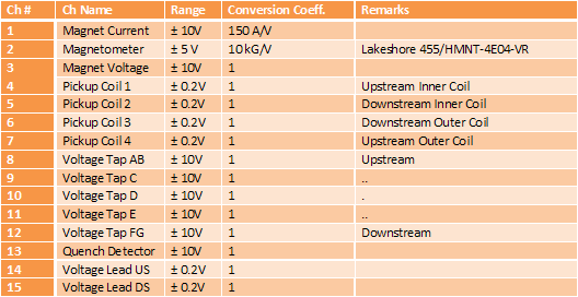
- Fast DAQ Channel List

- Connection for Coil 3
- Chan 21: Pickup 1
- Chan 23: Pickup 2
- Chan 25: Pickup 3
- Chan 27: Pickup 4
- Chan 13: Coil D1
- Chan 11: Coil D2
- Chan 15: Coil A
- Chan 7: Coil BC
- Chan 5: Field Probe O2
- Chan 31: Field Probe O3 (conditioned, delay)
- Chan 19: MPS current
- Chan 1: MPS voltage
- Connection for Coil 2
- Chan 21: Pickup 1
- Chan 23: Pickup 2
- Chan 25: Pickup 3
- Chan 27: Pickup 4
- Chan 7: Coil C
- Chan 13: Coil D
- Chan 9: Coil A
- Chan 15: Coil B
- Chan 5: Field Probe O2
- Chan 31: Field Probe O3 (conditioned, delay)
- Chan 19: MPS current
- Chan 1: MPS voltage